Empennage Constructions
Dimensions
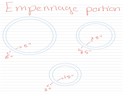
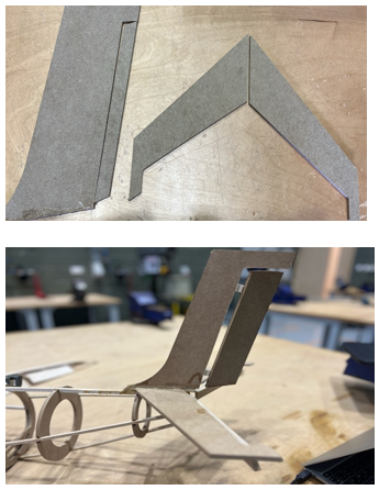
For the construction of the tail section, we followed a similar conceptual approach as we did with the fuselage, but with key adaptations to suit the tail's specific structural and aerodynamic requirements. The process began with carefully sketching the tail design on paper in order to determine accurate dimensions and proportions. This initial step allowed us to visualize the overall shape and make adjustments before committing to physical construction. We then cut out the paper templates and overlaid them onto wooden sticks to verify whether the shapes matched precisely and to ensure all components aligned properly with the intended design.
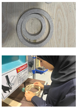
Once we confirmed that the paper templates and wooden mock-ups were consistent and accurate, we proceeded to convert our designs into digital form for CNC machining. Using the final measurements, we prepared files to cut out the tail components—particularly the circular cross sections or bulkheads—using CNC machines for precision and consistency. These machined parts served as the structural foundation of the tail.
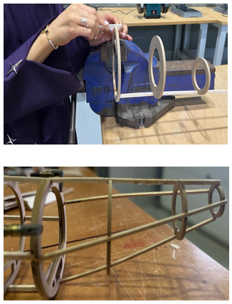
With the CNC-cut bulkheads ready, we moved on to the assembly phase. During this stage, we carefully measured the spacing between each circular cross-section and documented all measurements thoroughly in our notes to ensure correct alignment. We also created precise openings at the top of each bulkhead to accommodate the stringers. These longitudinal components were essential in maintaining the structural integrity and aerodynamic contour of the tail.
Due to the varying sizes and shapes of the bulkheads along the tail, extra attention was given to dimensional accuracy and alignment. Each component was individually checked and adjusted before assembly to avoid inconsistencies. By combining accurate planning, digital fabrication, and manual craftsmanship, we successfully constructed a strong and well-aligned tail section that mirrors realistic aircraft design practices.
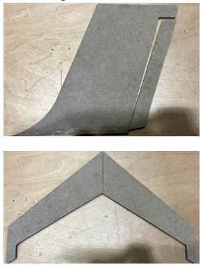
One of the critical stages in building our model aircraft involved the design, fabrication, and installation of the elevator and rudder, which are essential components for controlling pitch and yaw. Our process began with accurately calculating the dimensions of both control surfaces. To ensure functionality and realism, we referred to standard aircraft proportions and scaled them down appropriately for our model.
Once the dimensions were finalized, we created detailed sketches of the tail section, incorporating the elevator and rudder into the overall airframe layout. These drawings served as a blueprint for shaping the components. After several iterations and confirmations, we arrived at the final measurements that offered the best balance between aerodynamic functionality and structural compatibility.
For fabrication, we utilized CNC (Computer Numerical Control) machining to cut the components from lightweight and durable materials. CNC cutting ensured a high degree of precision and repeatability, which was crucial for maintaining aerodynamic symmetry and ensuring smooth operation. The elevator and rudder were then shaped and sanded to reduce drag and maintain a realistic aerodynamic profile.
To enable movement, we installed hinges along the fixed stabilizers—horizontal for the elevator and vertical for the rudder. These hinges provided a pivot point, allowing the control surfaces to move freely while remaining firmly attached to the stabilizer structures. Proper alignment and free movement of these hinges were vital to ensuring smooth actuation by the servo motors.
When it came to servo motor installation, we initially explored several mounting techniques. Our early ideas involved complex linkages and control horns placed at varying angles. However, upon consulting with our instructors, we were advised to adopt a more straightforward and effective method. The solution involved mechanically linking the elevator and rudder to their respective servo motors in a compact, unified assembly, and then firmly gluing the entire unit to the aircraft’s tail section.
This phase proved to be one of the most technically demanding parts of the project. Achieving precise alignment of the servo motors, control surfaces, and hinges was critical. Even minor deviations could cause binding, limited motion, or unbalanced control input. As a result, we invested significant time in carefully measuring, dry fitting, and adjusting the assembly before final installation. Accuracy and stability were key to ensuring that the control surfaces responded reliably to input from the Arduino system.
In conclusion, although this part of the construction was perhaps the most challenging, it was also one of the most rewarding. It required a combination of engineering judgment, fine craftsmanship, and teamwork. The final result was a robust and functional tail control system that faithfully replicates the real-world behavior of elevator and rudder systems in conventional aircraft.