Initial Wing Progress
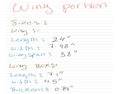
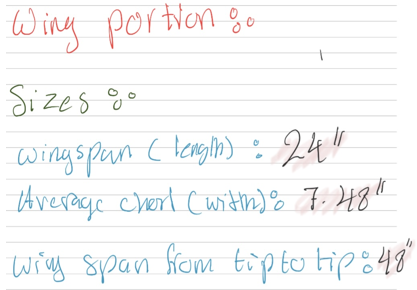
Initial Dimensions
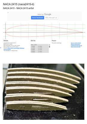
The first step in our project was selecting the most suitable airfoil, a crucial choice that impacts aerodynamic performance, lift, and stability. After extensive research, we chose the NACA 2415 airfoil, which has a 2% camber at 40% chord and 15% maximum thickness. This profile offers a balanced lift-to-drag ratio and stability, ideal for our educational model aircraft. We then designed the wing structure using scaled dimensions based on the NACA 2415, ensuring aerodynamic accuracy. CNC-cutting was used to precisely replicate the airfoil in the wing components. This foundational decision guided the development of the wings, ailerons, and overall aerodynamics, ensuring structural soundness and effective demonstration of flight principles.
The second step in our project was cutting seven airfoil sections using a CNC machine to ensure precise dimensions for our swept-back wing design. Since the wing required varying airfoil sizes for proper shape and performance, we first created scaled CAD models that accounted for the sweep angle and alignment. Once finalized, the designs were CNC-cut with high accuracy, producing smooth, consistent, and symmetrical sections. This precision was essential for achieving the correct wing sweep, which enhances aerodynamic efficiency, reduces drag, and improves high-speed stability—mirroring real aircraft performance. This step was critical in laying the foundation for accurate wing assembly and optimal flight characteristics.
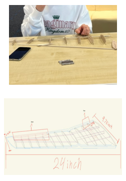
The third step in our project was determining the correct spacing between each airfoil section to ensure structural integrity and aerodynamic efficiency. Precise measurements and calculations were needed, as spacing impacts wing strength and airflow distribution. After multiple adjustments, we finalized a 2-inch gap between sections, maintaining the consistency of the swept-back design.
To aid assembly, we sketched the full wing layout on a flat surface, creating a detailed reference to align each airfoil accurately and maintain uniform spacing. This step was crucial for building a structurally sound, aerodynamically efficient wing, preparing us for the next construction phases.
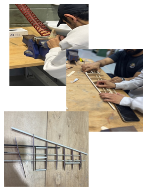
The fourth step in our project was drilling precise holes into each airfoil to insert support sticks, ensuring structural integrity and proper wing alignment. Using exact measurements, we marked and drilled consistent holes with a drill press to prevent misalignment.
With the support structure in place, we constructed and integrated the flaps and ailerons—key control surfaces for lift and roll control. We carefully cut, shaped, and sanded them to fit the wing design, ensuring smooth movement. After fitting them securely, we confirmed they moved freely, bringing us closer to a fully functional, flight-simulating wing.
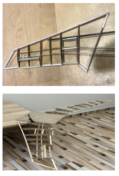
In the final step, we secured all components by gluing each airfoil and support stick to ensure the wing remained rigid and stable. Precise alignment and strong adhesive were critical for maintaining aerodynamic performance and structural durability. After allowing sufficient drying time, we constructed the wing box to firmly hold both wings in place.
The wing box was carefully measured, cut, and aligned to ensure a perfect fit and strong connection. We tested and adjusted the wing fit to guarantee stability under load. With this step complete, the wing was fully assembled and ready for integration with the fuselage—marking a major milestone in our aircraft's construction.